
U.S. Air Force Flex Fluid Lines

Team members required: Two
Description:
Hose assembly length is 11.5 inches (“A”). Assembly length is measured from middle of b-nut flat to middle of b-nut flat. Cutoff factor for each hose end fitting is .75 inches (“C”) (See figure 6)
References:
None
Tools and equipment list:
Qty 2, 11/16 combination wrench (OEX22B)
Qty 1, 13/16 combination wrench (OEX26B)
Qty 1, tape measure (TPMA12)
Qty 1, feeler gauge (0.23 - .046) (FB335)
Qty 1, 3/8" dr torque wrench able to torque 190-215 in lbs. (QD2R200)
Qty 1, 3/8" dr 11/16" crow foot (FCO22A)
Qty 1, hacksaw and blade (32 TPI) (HSG319, HSBM1232B)
Qty, 1 diagonal cutters (86ACF)
Qty 1, brass pick
Qty 2, leather gloves
Instructions:
A) Medium pressure PTFE hose buildup
1) Measure hose to required length
2) Wrap circumference of hose with masking tape at cutoff to prevent flare out of braid
**CAUTION** Do not overwrap tape
3) Cut off hose square using hack saw
4) Clamp sockets in vise.
**CAUTION** Do not overtighten vice on thin walled fittings
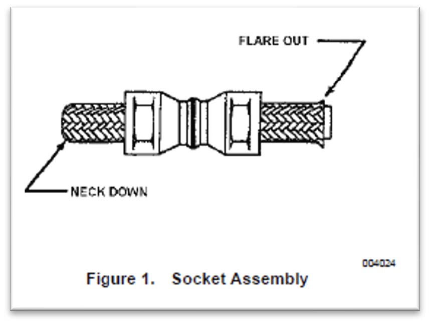
5) Insert neck-down end of hose into sockets using a twisting, pushing motion until hose is through the sockets, ensuring the ends are skirt to skirt. (Figure 1). Remove tape from hose and assembly from vise
6) Separate wire braid from tube. Seal pick is provided to aide in separation.
7) Insert sleeve between braid and outer diameter of the inner tube
**CAUTION** Do not allow wire braid to be caught between sleeve and inner tube. Do not pinch inner tube with sleeve
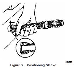
8) Complete positioning of sleeve by pushing sleeve against a flat surface until tube bottoms against inside sleeve diameter (Figure 3).
9) Check tube end to make sure it is bottomed against sleeve and wires are not trapped under sleeve. Trim excess wires as needed.
10) Clamp Nipple in vise (Note: Do not lubricate hose or nipple before insertion. Fitting components are dry film lubricated at time of manufacture.)
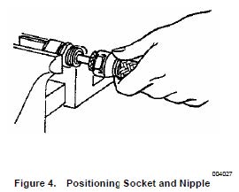
11) Size tube to sleeve by pushing hose over nipple until sleeve bottoms against nipple chamfer.
12) Check end to make sure sleeve is positioned properly.
13) Slide socket forward and thread onto nipple by hand
14) Reposition assembly by placing socket flats in vise.
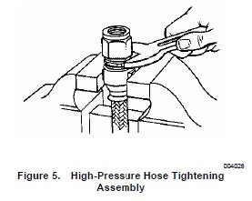
15) Tighten assembly by using a wrench on the nipple hex until gap between socket hex and nipple hex is 1/32 inch. Gap may vary from .023 to .046 inch.
16) Repeat steps 6 through 15 for fitting on the other end.
17) Inspect hose.
B) Medium pressure PTFE hose install.
1) Place hose into fixture assembly, threading coupling nuts on by hand.
2) Torque coupling nuts 190-215 in lbs. utilizing backup wrenches.
**NOTE** A back-up wrench should be used on nipple hex and on union inside fixture assembly to prevent kinking of hose and damage to aircraft.
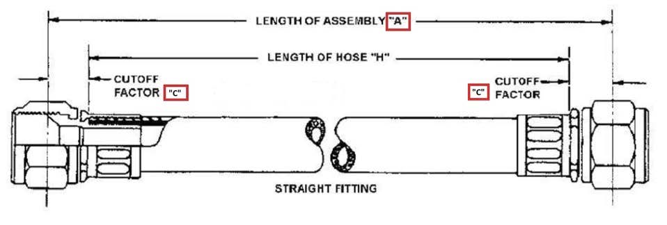
Figure 6
Scoring:
Scores will be calculated according to the standard score sheet.