|
Description:
|
Removal and installation of aircraft antenna using Av-DEC HI-TAK® Conductive Polyurethane Gasket and Av-DEC HI-TAK® StretchSeal® Polyurethane Rolled Sealant (PRS®).
This specification describes the method for removing antenna, aircraft surface preparation, and antenna installation using the Av-DEC HI-TAK® Conductive Polyurethane Gasket and HI-TAK® StretchSeal® PRS®. This method is to be used only for antenna gasket installations between an antenna and aluminum aircraft skin or ground plane.
|
|
Instructions
|
-
- Removal
- Remove fasteners from antenna.
- Use a phenolic, wooden, or plastic tool as a wedge between the antenna and the aircraft surface to separate antenna from the aircraft if needed.
- Once antenna is separated, cut the cable ties from the connector wrap and remove the StretchSeal® PRS®.
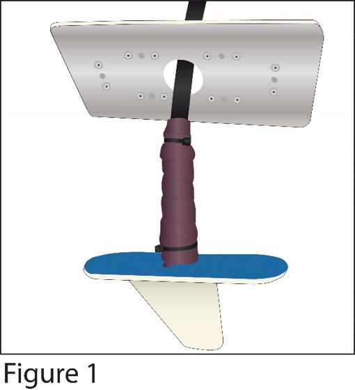
- Disconnect aircraft coax cable and peel antenna gasket from antenna/fuselage. Use isopropyl alcohol to remove any remaining residue. (Figure 1)
-
- Surface Preparation
- Inspect faying surface areas that will contact the Av-DEC gasket materials for corrosion.
- Surfaces that will come in contact with Av-DEC materials shall be wiped with a clean solvent-dampened cotton wiper, followed immediately by wiping with a clean dry cotton wiper to remove any remaining paint, dust, grease, fingerprints, and/or any other contamination prior to the Av-DEC material installation.
- Gasket Installation
- Av-DEC HI-TAK® Conductive Polyurethane Gaskets are supplied with protective release film on both sides of the gasket.
- Remove the gasket from the protective packaging, taking care not to fold or bend it. Leave release film in place until ready to install gasket.
- Verify that fastener holes and connector cutouts in the gaskets will align with the antenna when positioned for installation.
- Remove release film from the side of the gasket marked “antenna side” and position over the antenna.
- Beginning at one side or corner of the antenna, place gasket into position, carefully aligning gasket fastener holes with antenna fastener holes. Release film should remain on the exposed “aircraft side” of gasket until immediately prior to antenna installation.
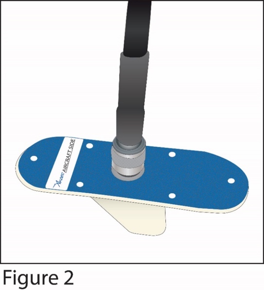
- Connect aircraft coax cable to antenna. (Figure 2)
-
- Sealing Aircraft Harness/Antenna Connector
- To apply the StretchSeal® PRS®, remove the PRS® from the package and unroll a small amount.
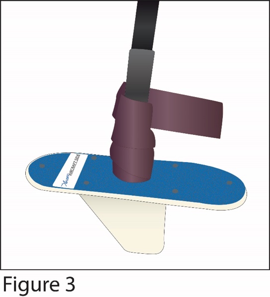
- Wrap the StretchSeal® PRS® clockwise around the mated connector with a 50% overlap while stretching the PRS® 25% to 50% to ensure a tight wrap. A tight wrap is necessary to ensure a proper seal. (Figure 3)
-
-
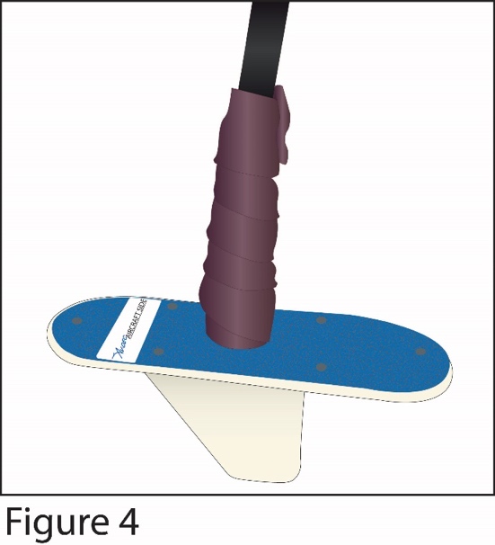
- Coverage shall be from the base of the antenna to at least ½” beyond the connector and onto the insulation jacket of the coax cable. Trim excess StretchSeal® if necessary. (Figure 4)
-
-
- Apply cable ties at the beginning and end of the StretchSeal® wrap around the connector and coax cable. Dress cable ties.
NOTE: Aircraft cutout hole must be at least ¼” greater in diameter than the connector outer diameter when using StretchSeal® PRS®.
-
- Antenna Installation:
- Remove the release film from the “aircraft side” of the HI-TAK® Conductive Polyurethane Gasket.
- Using existing fasteners, pre-position at least two fasteners through the antenna and gasket.
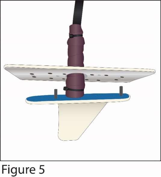
- Align fasteners at the correct locations on the aircraft surface. (Figure 5)
-
-
- Tighten each fastener 1-2 turns to hold the antenna in place on the aircraft.
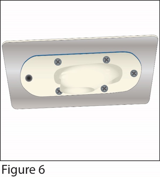
- Install all remaining fasteners except one. (Figure 6)
-
-
- Manually tighten fasteners to 10 in-lb. (Bonding check can be done at any time after initial torque of fasteners.) Wait at least 30 seconds and re-tighten fasteners as necessary.
- Bonding Check:
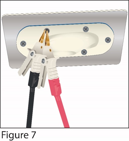
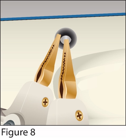
- 1. Measure the resistance between the antenna baseplate and the airplane skin with a milli ohm meter. Make sure that the resistance is 2.5 milli ohms or less, and, if not, retighten fasteners until the desired resistance is achieved. (Figures 7 & 8)
-
-
- Install the remaining fastener and manually tighten to 10 in-lb.
|